Started August 22nd, 2014
This project receives the values from Oregon wireless temperature/humidity sensors and records them. It is related to my liquid level sensor project and the power oring page. For a simpler data logger see Mini Logger.
The idea is that the logger powers up once an hour and receives data from all the sensors, saves it in EEPROM and then goes back to sleep. The logger is left permanently connected to a PC which is turned on during working hours, in that situation data can be uploaded to the PC and the batteries recharged; when the PC is turned off the logger uses battery power. The 'real time' Oregon displays work in a different way; they appear to power up when each sensor is predicted to transmit.
These are the parts of the system:
- 433 MHz receiver - discussed in the sensor project.
- Real time clock and EEPROM.
- Arduino Pro Mini
- USB serial interface
- Power Oring - covered in its own page.
- Battery charging - covered in its own page
- PC application software
Arduino Pro Mini
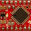
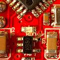
The little computer at the heart of this project. I cut a track to enable low power operation - this cut isolates the on board regulator and LED - it is to the top right of the 5 pin chip in the photo. I got this idea from somewhere on the web; by now there are a few examples; which may help if your Pro Mini is not the same design as this one; but also means I can't find the original reference. Current consumption of the whole project when sleeping is under 2 micro Amps. For some designs of Pro Mini cutting the track may not be enough; see the Arduino32768 page.
Photos show Arduino Pro Mini and cut track; click for full size
The Pro Mini has no USB interface, instead it has pins for a TTL serial interface. The lack of USB is an advantage because it allows me to insert the power oring components between the Arduino and the USB interface. I use one standard interrupt for the Real Time Clock, another for the radio receiver. But I also need one for spotting when the USB voltage is lost, to gain this I used the PCChangeInt library.
I used the Serial Command library to give me commands for talking to the logger from the standard Arduino IDE serial window. These let me adjust the clock and read values from the memory.
The idea is to have a 'base' time and a period for how often data is saved. Every reading can then be identified by a number - the number of periods that have elapsed since the base time. Readings wrap around in memory. Doing things this way there is no need to store a time for each reading.
The AVR ATMega chip has some EEPROM of its own, this is used to store settings, for example the base time and period.
USB serial interface
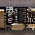
The familiar component that has a USB connector on one side and a TTL serial interface on the other. Often these are based on the FTDI chip. I used one based on the CH340G.
Photo shows USB interface; click for full size
Real Time Clock
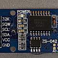
I bought a board from ebay containing a DS3231 real time clock (RTC) and AT24C32 4K byte flash memory chip. This board uses the I2C bus. The RTC has its own lithium battery to keep the clock running. One might think that is the end of power supply problems. Not so, the board has a Vcc pin used to power the memory chip and the clock whilst talking to it. It uses a surprisingly large amount of power, some 10 mA. This is because it has an LED indicator and a charging circuit for the battery (important see below). In addition there are two banks of four 4K7 pull up resistors on the interface pins.
My idea was to power the RTC board from an Arduino output pin when I needed to. But I found that powering up the board (after the first time) would make I2C hang. I got round that by editing the twi library and removing the code which enables pull ups for the I2C pins.
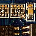
The plan was to put the Arduino to sleep and then use the RTC interrupt output to wake it. The RTC has an FET that pulls down when an alarm goes off. However that won't work because of the pull up resistors (one of which is on the FET interrupt output). They're all joined together (obviously at the Vcc end), and with Vcc disconnected they act as one large pull down resistor. The Arduino's built in pull up is not strong enough to overcome this, and even if it was I don't want to waste lots of power. I cut a track on the RTC PCB to remove the pull up resistor on the interrupt pin. These RTC boards are apparently not designed to use little power whilst periodically waking up a system.
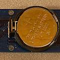
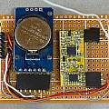
Photos show RTC back, front and cut track; click for full size
One vendor had (it has now vanished) an archive which contains datasheets, code, and a schematic. The Edward Mallon underwater sensor blog page addresses similar issues.
The code in the vendor archive for controlling the RTC is from Eric Ayars, and I have used this. I found a bug fix on the web which I applied and I have also fixed another problem with it.
The vendor archive code for writing to the memory chip is apparently from Using Arduino with an I2C EEPROM and uses the Wire library, a lot is made in various places of only being able to write 28 bytes at a time. The Wire library has a 32 byte buffer, and uses 2 bytes of it for the address to write to. Fixing this means creating your own local wire library, and changing the buffer size in the header from 32 to 34. However the Wire library is built on the twi library, that also has a 32 byte limit. I made a local copy of the Wire library called wire2 and put in it renamed copies of wire.h, wire.cpp, twi.h and twi.c from C:\Program Files (x86)\Arduino\hardware\arduino\avr\libraries\Wire and the utilities folder inside it.
The battery
You use the information that follows is at your own risk. Seemingly these boards are often supplied with rechargeable cells, mine came with a primary cell CR2032, you can see this in the photo. The board has a charging circuit consisting of a 200 Ω resistor and a diode. Charging primary lithium cells is generally thought to be a bad idea - they may explode. In fact the makers of the DS3231 have taken the trouble to have it certified as not being able to charge the battery. Good practice is to use two reverse polarity protection diodes.
To put it another way "cheap ebay clock boards are fire hazard!".
When I got the board I thought low current charging would do little harm as with other primary cells and ran the board connected to a five volt supply for many months - there was no sign of the battery getting hot. Eventually I examined the battery and found it had a voltage of 3.7 V which was held for days. Does this mean it really was a rechargeable lithium cell, or had the months of charging changed it. Another similar unused board had an identical battery with a voltage around 3.3 V, typical of a CR2032. If one were to run these boards on 3.3 V I would not expect the battery to be charged due the diode forward voltage drop.
Eventually I disconnected the resistor in the charging circuit on the board (top right marked 201) and fitted a genuine CR2032 battery.
Why I did that is another story...
Accuracy was originally similar to that of a cheap quartz clock, 5 seconds per 24 hours. Adding a clock crystal to the Pro Mini (see Arduino 32768) and not bothering with the RTC would have been simpler and given the same result. However the DS3231 is supposed to be much more accurate than this (see this discussion) because it features a temperature compensated crystal oscillator (TCXO). The manufacturer datasheet claims a couple of minutes per year (a third of a second per day) over a wide temperature range. There are 31.5 million seconds in a year, the error over a narrower temperature range is quoted as 2 ppm. Comment on the web often expects ebay DS3231 boards to be substandard yet they're usually found to be accurate.
There is a register to trim the clock frequency to cope with crystal ageing (aging) which has a range of +/- 127 0.1ppm units or just over +/- 1 second per day. I've made a trivial extension to the library to allow this register to be written and read.
I noted that whilst the PC was supplying power the clock was accurate, only when left on its own battery did it gain. That led me to measure the battery voltage and discover it was 3.7 V. After disconnecting the charging circuit and installing a new battery the clock kept much better time.
Change of clock frequency with voltage is quoted as 1 ppm; the change in voltage from 3.7 to 3.3 V would not be enough to explain the gain of 5 seconds per day. 3.7 V is also an acceptable value for the battery voltage.
The maker of the DS3231 has a note Power Considerations for Accurate Real-Time Clocks which explains how often the chip attempts to compensate for the temperature. The minimum and default period for temperature compensation is every 64 seconds.
I tried various things, and thought about fluctuations in voltage or temperature, but the only conclusion I came to is that the CR2032 being charged to 3.7 V makes the clock run fast, whilst a 3.3 V battery without the charging circuit gives amazingly accurate time keeping.
Eventually I configured the DS3231 1 Hz square wave output and used the code on my GPS page to measure its variation. I found that a few seconds after the change to battery power (presumably the next temperature compensation event) the clock would speed up when using the 3.7 V battery.
Construction
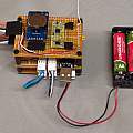
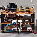
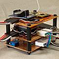
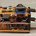
Photos show construction; click for full size. The first set of four show the assembled device.
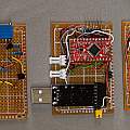
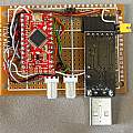
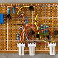
The next set show the three boards. Photo 2 is of the RTC and 433 MHz receiver board. Photo 3 the Arduino Pro Mini and USB interface board - the right hand jumper is used to isolate the reset line to the Arduino, the top jumper allows operation without the power supply board. Photo 4 shows the power supply board which has the battery charging circuit (two transistors top left) and power or circuit (four transistors bottom right). The white polarised connectors are known as KF2510-3P; commonly used for fans on PC motherboards; it seems one standard is to have the middle pin positive. The right hand one is for the battery; the middle one takes in power from the USB interface and supplies power to the rest of the project; the left hand one has pins for measuring the battery voltage, signalling if USB power is present and enabling battery charging.
PC Application Software
This can be downloaded from the link below (including source code). It's a crude Windows command line (console) tool. Gems in the source code (copied from others) include how to connect to the Arduino without generating a reset, enumerating COM ports on Windows then picking the right one and talking to the Arduino via the serial port. A text file of readings is maintained; new values since the last time the program was run are added to it.
I used a lot of freely available software. Credit to the people who wrote it and made it available.
- LowPower library by Rocket Scream Electronics
- Decoding the Oregon Scientific V2 protocol by Dominique Pierre
- Oregon Scientific sensors with Raspberry PI by Paul Pinault
- ATMega 328 Secret volt meter by Tinker It
- ATMega 328 Secret thermometer Tinker It
- DS3231 Real-Time Clock by Eric Ayars
- Using Arduino with an I2C EEPROM
- PinChangeInt Library
- Serial Command library by Stefan Rado
- Time library by Michael Margolis
- Enumerating serial ports by Naughter Software
- Oregon Scientific RF Protocol Description
- Power saving techniques for microprocessors - Nick Gammon
- millis ( ) overflow ... a bad thing? - Nick Gammon
- Arduino Pro Mini Schematic
- An Arduino based underwater sensor project - Edward Mallon
- ATmega ADC
- Archive of Arduino 'Receiver' (name for the Logger code) sketchbook and libraries - in other words all the sources for the Arduino part of this project (1st December 2014).
- Archive of PC application code - this is a Microsoft VC++ 6.0 project folder (1st December 2014).
