August 2014
I had a project that I wanted to run using batteries but also from USB power. It is permanently connected to a PC which is powered on during working hours, and turned off the rest of the time. The idea is that when the PC is powered up the project runs off USB power and recharges its batteries, the rest of the time it uses the batteries.
I invented the requirement that no power should be wasted by the circuit which switches from batteries to USB. The sensible solution is a couple of low leakage Schottky diodes (BAT85S was my choice). But they have a voltage drop of about 0.3 V and that would be power wasted and mean the signal levels would not quite match.
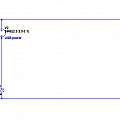
Click on images to display full size. First sharing power with two diodes. Second with diodes in the negative supply.
My project uses 5 V when talking to the PC, but can run off a lower voltage. I decided to use three NiMh batteries. The design then hangs on special cases. The USB nominal voltage is 5 V, but might reasonably go as low as 4.8 V. The batteries might cover the range 3.6 to 4.5 V. This gives room to say USB voltage will always be greater than battery - but the difference is small. If the situation had been different - for example four NiMh could have gone both above and below 5 V - the design would have been too.
To switch the power I used N channel MOSFETs, these are cheaper and more common than P channel, but using them means switching the negative power supply, rather than the more common way of switching positive power. I used the 2N7000 - but I only need around 20 mA.
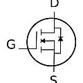
MOSFETs have a body/parasitic/substrate diode. Usually this is reverse biased and the gate voltage allows current to flow. However they can be used with the diode forward biased and the gate voltage then reduces the forward diode voltage drop. This is known as "third quadrant operation" and there is a common circuit for reverse polarity protection of battery operated devices which uses MOSFETs in this mode; with the advantage over diodes of a lower volatge drop.
In common usage the FET drain is positive with respect to the source. In the power switching role here the FETs will have both drain positive with respect to source as well as the opposite. This is because they can be supplying power from one source, or that source can be turned off in which case they're expected to block power flowing back into it. I don't want the battery to power the PC.
From these points I ended up with two FETs, one to switch power from USB and one from the battery. When an FET is supplying power its substrate diode is forward biased, which means its source is positive with respect to its drain. Ignoring the gate signals, the circuit amounts to replacing two diodes with two FETs, in such a way the FET substrate diodes replace the conventional diodes. This circuit will work, the forward drop is around 0.6 V. It provides a limit on how badly the circuit can perform. If the switching signals fail completely then power will still be supplied to the load from which ever source has the higher voltage.
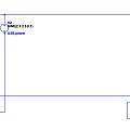
Click on images to display full size. First shows substrate diode in FET (between Drain and Source). Second sharing power with two FETs acting as diodes. Not a practical circuit
Talking of what can go wrong, if instead of both FETs being off, both are on, the result will be that power flows either from the battery back into USB or from USB into the battery.
One switching logic is to look at the USB voltage and if it is greater than X (a fixed selected value) turn off the battery power and turn on USB. I can monitor the USB voltage because it is either disconnected from the load or the load is running from USB and the battery is disconnected.
Click on images to display full size. Power or circuit with FETs which switch when the USB voltage passes a set value, which is determined by the Zener diode. Note that this circuit would not work if the battery voltage was higher than USB - in that case the diodes in the FETs would conduct using the highest voltage available. R2 and R5 help turn off one FET before the other turns on.
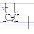
An alternative is to compare the battery and USB voltages and use whichever is higher. This invokes the special case - battery voltage will always be less than USB. I believe this is the best circuit and I have used it in my project.
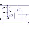
Click on images to display full size. Power or circuit with FETs which switch in the highest voltage. The two bipolar transistors could be looked at as two diodes which monitor the current passing through themselves. Signals can be taken from their collectors indicating which power source is in use.
All of my experience with electronics was in the 1970s. Now being in the 21st century I decided to use emulation to test my circuits. Spice came to mind. I set off with ngspice on Linux. I learnt two hard lessons, there always has to be an earth node, and sub-circuit components need an X prefix. I then moved to LTspice running under Wine, and I have found this to be good. A zip file containing LTSpice versions of all the circuits on this page can be downloaded from the link below.
Note that I modelled the USB power as a sine wave voltage source, to give something to watch. In reality the USB voltage is what will vary, although probably not this nicely.
What happened
See Ideal Diode for later related material. I also became aware of the TPS2113 Autoswitching Power Multiplexer.

