Being about the battery charging component of my wireless sensor Logger project.
How do you find the battery voltage. Simple, connect an analog input to it. That's what I thought. I had one worry which is that the battery voltage could lie outside the power rails of the Arduino. That can happen due to power losses in the FETs or if the switching circuit fails and there is a diodes worth of voltage drop across the FET. My solution was to connect the battery via a large (3 MΩ) resistor - thinking that would limit any currents through static protection diodes on the inputs. It should be OK because the analog inputs have a huge input impedance (100 MΩ). But I later discovered the recommended impedance of the input source is 10 KΩ. This is due to multiplexing the ADC between inputs and capacitances in the ADC (see ATmega ADC). I eventually restored accuracy by adding a 0.1 uF capacitor across the input; this gives a big time constant but for this application it is not a problem.
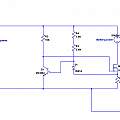
There is only a small voltage difference with which to charge the three NiMh cells from 5 V. Around 50 mA was the maximum charging current I wanted. The circuit used to supply a constant current is shown below; click to display full size.
When charging current to the battery flows through the FET. R1 is a current sense resistor. When the voltage across this is high enough the FET is turned off by the transistor Q1 reducing the current flowing into the battery. The standard version of this circuit uses the voltage across the sense resistor to directly turn on the transistor; that takes around 0.6 V. The addition of the diode D1 allows a smaller voltage across the resistor to be effective. The diode also provides some stability with temperature variations. It is possible to bias the transistor with two resistors, but that has the stability problem, that a lower supply voltage gives a bigger current, which in turn may lower the supply voltage.
I used a 500 KΩ variable resistor for R3 and adjusted it for the current I required. Changing R3 alters the current through D1 and the voltage across it. Current limiting starts when the voltage across the diode plus that across R1 is enough to turn on the transistor Q1. R4 limits the current through R3 (when R3 is adjusted to near zero).
As part of the sensor Logger, R2 and R4 are connected to an Arduino output pin; taking that high enables charging.
An archive with the LT Spice model of the circuit can be downloaded below.
I used a lot of freely available software. Credit to the people who wrote it and made it available.
