Ultrasonic Direct
Started 16th September 2018
The idea of this sketch is to connect the ultrasonic transducers (taken from a HC-SR04) direct to an Arduino. I am only interested in measuring small distances, say 200 mm.
The transmitter is connected between digital pins 3 and 11. These are the output pins associated with Timer 2, and it is used to produce anti-phase signals on them.
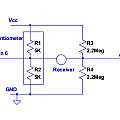
The receiver requires some passive components to shift its output level to mid-way between the supply rails. These take the form of a bridge. One side of the bridge is a 10 KΩ potentiometer, the slider connects to digital pin 6 and the receiver, and the other two pot connections go to the supply rails (Vcc and Gnd). The other side of the bridge is formed from two 2.2 MΩ resistors connected in serial. The common connection goes to analog pin 1 and the receiver, and the other two connections to the supply rails. Circuit diagram below.
The pot is twiddled to achieve zero DC voltage across the receiver.
The analog comparator, capture register and Timer 1 are used to record events where the outputs of the receiver change relative polarity.
The ATMega 328p is clocked at 16MHz, it is convenient to measure time in processor clock ticks (clocks) which are microseconds/16 in duration. The code sets up the output period as half period durations in units of clocks. A frequency of 40KHz has a period of 25 μs, which is 400 clocks, or a half period of 200 clocks. By experiment the transducers have a maximum response at a half period of 193.
The sketch transmits a continuous wave and prints out the phase shift (in microseconds/16) of the received signal. Results are very sensitive to air currents, the effects of breathing over the path of the sound can be seen.
Download
- Archive of Arduino code for direct connection phase shift measurement - (20th September 2018)
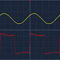
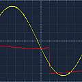
'Scope images. For these the period is 386 clocks or 24.125 μs and the ATMega is running from 3.3 V. The signal is being reflected by an object 100 mm away from the receiver and transmitter, total path length 200 mm. The first picture shows transmit (red) and receive (yellow) both at 1 V per division and 5 μs. The second picture has a receive (yellow) scale of 200 mV per division. The distance between the cursors (cyan) is 21.3 μs. That gives a phase shift of 21.3/24.125 = 0.88 or in clocks 0.88 * 386 = 341. The sketch output was 345.
It is also possible to use this technique to transmit a short pulse and then watch for the echo arriving back. The Timer 2 match interrupt is used to count cycles and then stop transmission. Timer 1 is allowed to overflow and the corresponding interrupt used as a timeout - preventing waiting for an echo that is never going to arrive.
Download
- Archive of Arduino code for direct connection echo measurement - (27th September 2018)
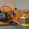
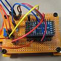
Build of the circuit.
David Pilling's Wiki
Set view
