Started 23rd May 2017
Playing with strain gauges. I make use of strain gauges and the HX711 for 3D printer Z axis probing.
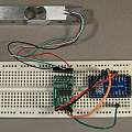
Photo shows the standard issue ebay load cell connected to an Arduino Pro Mini via a HX711.
Whilst this setup works, actually constructing the Wheatstone resistance bridge on a breadboard is problematical because the contact resistance of the board and the usual pins varies on a scale greater than the changes in resistance being measured.
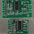
There is more than one design of HX711 breakout board. The bottom design XFW-002 has a link to switch between 10 and 80 Hz mode, it is also double sided and smaller, so it fits better in a breadboard. It seems to be close to the SparkFun schematic [7] whilst the other design follows [5]. Perhaps the significant difference is the larger time constant on the inputs to the top board.
A trap lies in wait on the top board, it appears the RATE pin (15) is connected to nothing, and a simple link to the pin above it (pin 16) which is connected to Vcc is all that is needed to enable 80 Hz mode - however the RATE pin has an invisible link to Gnd, so any link shorts Gnd to Vcc. Instead one has to mess about bending pin 15 away from the pcb [8] and then linking to pin 16.
Despite all the negatives, based on a sample of two, the top board appears to be less noisy. HX711 noise is greater when running at 80 Hz. Solid construction, for example not using push fit connectors helps reduce noise. At 10 Hz the top board noise is about 100, the bottom board is 1000 and running at 80 Hz increases the bottom board noise to 3000 - these numbers are un-scaled output values using Channel A input with a gain of 128.
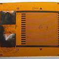
I obtained some BF350 strain gauges, these have a resistance of 350 Ω. I set off by 3D printing my idea of a load cell and attaching the BF350 with double sided sticky tape. This stuck to the strain gauge a lot better than than to the load cell. I managed to damage a couple of strain gauges removing the tape - in the first photo below it can be see that the connection to the solder pad (inside the strain gauge) has broken. Results for changing resistance when using 'super glue' (cyanoacrylate) to attach the BF350 were a lot better.
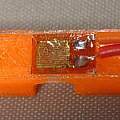
Soldering to a BF350 not attached to anything makes the plastic film warp, subsequently trying to flatten the plastic to stick the BF350 to something can break the internal wiring. I came to the conclusion it is best to stick the BF350 to the object and then solder to it. The contacts get glue on them, but it is easy enough to solder through the glue. It is then essential to provide strain relief or else the wires will pull the contacts off the strain gauge.
- An Arduino library to interface the Avia Semiconductor HX711 24-Bit Analog-to-Digital Converter (ADC) for Weight Scales
- The original HX711 library
- SparkFun Load Cell Amplifier - HX711 library
- SparkFun Load Cell Amplifier HX711 Breakout Hookup Guide
- HX711 Bridge Sensor Digital Interface Module (HCMODU0073)
- A HX711-based MilliOhm Meter
- SparkFun HX711 schematic
- Arduino thrust tester
Contributed Links:


