This is a Raspberry Pi hat which takes three stepper motor driver carrier boards - of the common Allegro A4988/TI DRV8824/Pololu/StepStick type - available for around £/$/€ 1 on ebay. Software for this is Stepper Pi.
The three motor drivers are called Tilt, Rail and Pan. Sometimes it is easier to number them 0, 1, 2. For each motor there is a driver - so Pan pin 16 is pin 16 on the respective driver carrier board. For each driver there is a step pin (to make the motor move), direction (controls which way it goes), enable (turns on power - high means off) and three pins which set the size of the microsteps (MS1, MS2, MS3).
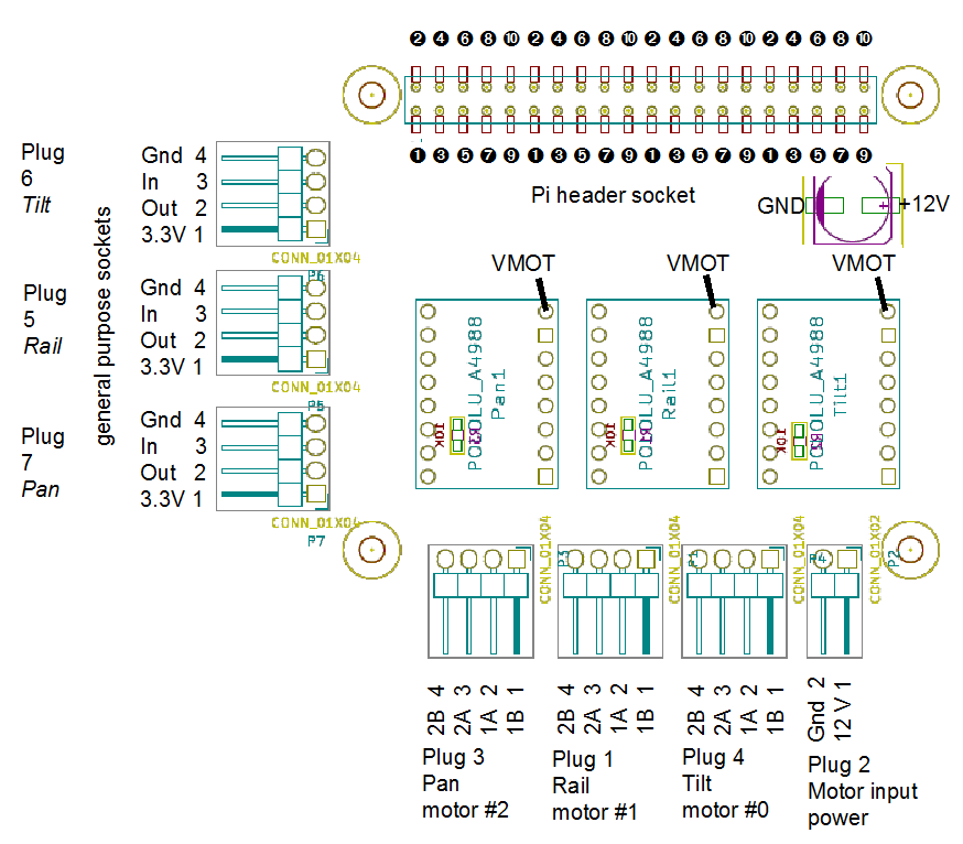
The hat also has three general purpose plugs/sockets (numbered 5, 6 and 7), two pins on each of these carry power, the other two pins are configured as an input and an output. Each general purpose socket is loosely assigned to a motor. The idea is that they'd typically have the limit switch for that motor attached. On the schematic plug 7 is Pan, plug 5 is Rail and plug 6 is Tilt. Pin 1 on each socket is 3.3 V and pin 4 Gnd. Below "Tilt input" means the general purpose socket 6 pin 3, it has nothing to do with the motor driver carrier. The general purpose sockets could be used for anything and need not be related to motors; giving them the motor name is not to be taken too seriously.
Another connector - plug 2 carries motor power, 12 V and Gnd, independent of the Pi power rails.
The PCB is double sided and uses three surface mount resistors and one capacitor, however the design only has power lines on the top surface and can be easily built on a single sided board using conventional through hole components.
The table at the bottom of the page shows the relationship between the pins on the Pi header, what they're connected to on the hat, the function and the Wiring Pi pin number. Wiring Pi numbers are needed for things like the read and write commands provided by Stepper Pi.
Photos of various driver carrier boards.


A snag with the 7th April version below, is that the 'Front copper' layer is what should be printed on the back of the board (and the 'bottom copper' layer should be on the top). Consider the stone age single sided printed circuit board. On one side are through hole components, on the other copper. The copper side is the bottom, because the board can actually sit level on this. The component side is the top, it is irregular because the components are different sizes.
The standard definition is front/top and back/bottom - that it matters is a result of there being a convention of looking at layers from above the front/top, regardless of if the layers are on the top or the bottom of the board.
The result of this oddity is that text in the silk screen for this version will come out mirrored if the board is printed correctly.
Why did I mix this up. The hat template includes a surface mount header socket. For surface mount designs it is conventional to have components and copper on the top of the board. However a hat is often a double sided design, one can say the surface mount socket is on the front and in that case design the back of the board with components on the bottom - the footprints for those components will not be the usually available ones.
The alternative is to design the board with an inverted version of the surface mount socket on the bottom and conventional components on the front. This is what I have done in the second version of the board dated 22nd April. This archive also includes the set of Gerber files I sent to Itead for PCB production.
The first two photos show the board I produced using the negative photo-resist method. This is a single sided version and I had to fix many broken and shorted tracks. The next two photos show the Itead board - which is vastly better.


I have a number of the Itead boards to give away. But you will have to supply the components - see [3] for the 40 pin header socket.
If I had the chance to do it all again...
For the Tilt general purpose socket I used wiring Pi pins 8 and 9 (Pi header pins 3 and 5, SDA and SCL) these it turns out have 1.8 K pull up resistors on the Pi board. It means the TCRT5000 reflective sensor will require its LED to be run at a higher current so that its transistor will be able to pull down the pin. Usually I have used a 150 Ω resistor for the LED giving a current of just over 10 mA along with a 10 K load resistor. For the sensor connected to the Tilt socket a 56 Ω resistor (30 mA) gives similar range; the 10 K load resistor could be omitted.
Thicker current carrying traces
Leave in the cut-outs on the hat for the connectors on the Pi
Mark the VMOT pin of the drivers on the silk screen. Mark + and - power on the connectors.
Individual decoupling capacitors for each driver inside the socket footprint.
Download
Sources
| Pi pin | Connection | Function | Wiring Pi pin | ||
| 1 | NC | ||||
| 2 | NC | ||||
| 3 | Plug 6 pin 3 | Tilt input | 8 | ||
| 4 | NC | ||||
| 5 | Plug 6 pin 2 | Tilt output | 9 | ||
| 6 | NC | ||||
| 7 | NC | 7 | |||
| 8 | NC | 15 | |||
| 9 | NC | ||||
| 10 | Plug 5 pin 3 | Rail input | 16 | ||
| 11 | Plug 7 pin 3 | Pan input | 0 | ||
| 12 | Plug 5 pin 2 | Rail output | 1 | ||
| 13 | Plug 7 pin 2 | Pan output | 2 | ||
| 14 | NC | ||||
| 15 | Pan pin 15 | Step | 3 | ||
| 16 | Pan pin 16 | Direction | 4 | ||
| 17 | 3.3 V | ||||
| 18 | Pan pin 9 | Enable | 5 | ||
| 19 | Pan pin 10 | MS1 | 12 | ||
| 20 | NC | ||||
| 21 | Pan pin 12 | MS3 | 13 | ||
| 22 | Pan pin 11 | MS2 | 6 | ||
| 23 | Rail pin 15 | Step | 14 | ||
| 24 | Rail pin 16 | Direction | 10 | ||
| 25 | Gnd | ||||
| 26 | Rail pin 9 | Enable | 11 | ||
| 27 | NC | ||||
| 28 | NC | ||||
| 29 | Rail pin 10 | MS1 | 21 | ||
| 30 | NC | ||||
| 31 | Rail pin 12 | MS3 | 22 | ||
| 32 | Rail pin 11 | MS2 | 26 | ||
| 33 | Tilt pin 16 | Direction | 23 | ||
| 34 | NC | ||||
| 35 | Tilt pin 9 | Enable | 24 | ||
| 36 | Tilt pin 15 | Step | 27 | ||
| 37 | Tilt pin 11 | MS2 | 25 | ||
| 38 | Tilt pin 10 | MS1 | 28 | ||
| 39 | NC | ||||
| 40 | Tilt pin 12 | MS3 | 29 |