I needed to control a stepper motor for a macro rail - a device that can repeatedly move a DSLR camera tiny distances to allow high magnification photographs to be produced using "focus stacking".
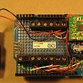
The solution was an Arduino shield with an Allegro A4988 stepper motor driver board. The Arduino code understands a set of two letter commands sent via the serial interface. A later development is a move to the Raspberry Pi - see Stepper Pi.
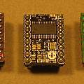
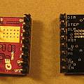
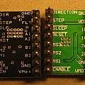
Initially the shield was used with an Uno, but later to get more speed it migrated to a Due. Eventually the A4988 was replaced with a Texas Instruments DRV8824 which offers better performance.
Another aspect of the hardware was using a reflected infra-red light sensor (TCRT5000L) to stop motion at the end of the rail.
The final change to the code was allowing it to execute sequences of commands autonomously - I used this to do time-lapse photos with the code triggering the shutter release between stepper motor movement. This stepper motor was rotating the object in the time-lapse sequence (and was nothing to do with the macro rail).
The main control application was written in Visual Basic (spit) and runs on Windows. The glue between these and the Arduino is a Windows DLL (see Stepper DLL). The initial version connected to the Arduino via a (USB) COM port, a later version also works via a TCP/IP socket.
Each motor full step is divided into a number of microsteps, and this number of microsteps can be set. More microsteps gives smoother movement and greater precision (but less torque). Since one may wish to change the number of microsteps whilst using the rail, an effort is made to make the units used independent of the number of microsteps.
Typically units are 1/16th of a step. For example a motor with a full step size of 1.8 degrees has 200 full steps per rotation or 3200 (200 * 16) units per rotation. In what follows it would require a move of 3200 to make it turn once. This is independent of the number of microsteps in use by the driver.
Similarly a speed of 3200 would make the motor turn once per second, again independent of selected microstep size.
For this speed of 3200 if a step size of 1 was selected 200 pulses per second would be sent to the motor driver. If a step size of 16 microsteps was selected 3200 pulses per second would be sent to the motor driver. The user of the interface described below does not see this complication.
The advantage of this approach is that the number of microsteps per full step can be changed without having to change anything else for results (distances, rotations per second) to remain the same.
It is possible to set the "base scale", in the above the number 16 (the units in other words), but when using ti mode (i.e. the hardware is using the TI chip), 32 makes more sense since the TI chip allows 32 microsteps.
The simple Arduino model of interrupts is followed, interrupt 0 is on pin 2 and interrupt 1 on pin 3.
Photos show the shield and various driver carrier boards.
Downloads:
- Arduino code Stepper2 - (Version: 1.12 20/11/2014)
- Circuit schematic diagram
- Serial Command library by Stefan Rado
- Enumerating serial ports by Naughter Software
- AccelStepper by Mike McCauley
Arduino commands enter in serial command window
pw [0|1|2]
Set power mode 0 = off, 1= on, 2= automatic
mv <distance>
Move, returns a message when move is complete including new position
sp <speed>
Set speed in steps per second.
ac <acceleration>
Set acceleration in steps per second per second
ss [1|2|4|8|16]
Set number of microsteps, in ti mode 32 is also allowed
xx
Stop
ps
Return current position
ds
Return distance to go
rd <pin>
Read state of an Arduino pin, returns value
wr <pin> <value>
Write a value to an Arduino pin
ai [0|1] <mode>
Arm interrupt zero or one, mode is usually 2 - interrupt on 1 to 0 transition, FALLING. The result of an interrupt going off is to stop the motor. They're intended to be used by the reflected light sensor.
is
Return debug info on interrupt state
sc <position>
Set the current position value. Allows zero point of values returned to be changed.
rs <speed>
Make the motor run continuously at the given speed. Use a value of zero to stop.
ve
Return software version
ri [0|1]
Remove interrupt
ti
Enter Texas Instruments mode. Enables 32 microstep mode.
bs <value>
This sets the base scale, default is 16. Another explanation for this it is the number of microstep units in a full step.
Resolution can't be less than the bs value. So if it is set to 16, the motor can move in 1/32 nds (ss =32) but will always end up on a 1/16 th position.
ts <2|3>
Return:
0 sensor connected 1 sensor not-connected
di <time>
Debounce interrupts. Parameter is time in ms for which the pin associated with an interrupt must be zero before the interrupt will cause the motor to stop.
dl <time>
Whilst executing commands pause for time ms.
rc <n>
Start executing program n. Programs are held in the array program[] and the first one is a NULL pointer so rc 0 stops execution.
An interesting problem
This code was in the original 2014 version, but resulted in a hex file that could not be uploaded to an Uno in 2016.
#ifdef __AVR__
#include <avr/signature.h>
#endif


void cmdprocessor()
{
 #ifdef __AVR__
 char temp[32];
 sprintf(temp,"pr 0x%02x%02x%02x",SIGNATURE_0,SIGNATURE_1,SIGNATURE_2);
 Serial.println(temp);
 #else
 Serial.println("pr 0xFFFFFFFF");
 #endif
}

avrdude: ERROR: address 0x840003 out of range at line 1281 of C:\Users\David\AppData\Local\Temp\build4255321523040323625.tmp/Stepper2.cpp.hex

avrdude: read from file 'C:\Users\David\AppData\Local\Temp\build4255321523040323625.tmp/Stepper2.cpp.hex' failed


https://sourceware.org/ml/binutils/2015-02/msg00003.html
http://www.avrfreaks.net/forum/solved-error-address-0x810010-out-range


