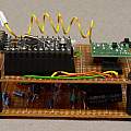
Following from the wireless temperature sensor the thought occurred, if it can be made to use so little power, then why not use solar cells and avoid all the hassle replacing batteries. The Oregon sensors consume lots of batteries and modern expensive branded AA non-rechargeable batteries seem to be good at leaking and destroying electronics. When I was a lad 'leak proof' versions of batteries actually existed and cost a few pennies extra.
The claim for the wireless sensor design is a power consumption of 75 μW (25 μA at 3 V). One could have a solar panel the size of a house roof and use it to power a modern PC - but my aim was to use small solar panels - the type of thing that can be found in garden lights (see Solar Stuff) - typical power output 4 mW.
The problem is that the sun does not always shine. Here in the North of England, daylight may be as little as six hour in Winter, and there is often heavy cloud. On the other hand in Summer there can be many hours a day of bright light. Translation - often the solar cells will not provide enough power, often they will provide too much
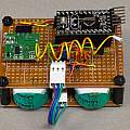
I set out to try some things. Firstly I built a standard sensor - to the design of the wireless temperature sensor consisting of an Arduino Pro mini modified for low power operation and with the addition of a 32768 Hz crystal. I fitted an MCP9700 temperature sensor instead of the BMP 180 - on the grounds it would need no messing about with I2C.
To these sensor boards I could add various power boards.
Caniballised Solar Powered Garden Light version
The first design for a power board was inspired by the garden lights I pulled to pieces (see Solar Stuff). These contain almost all one needs, a rechargeable NiMh battery, a solar cell, and the yx8018 integrated circuit. The yx8018 is a boost converter - efficiency is around 80%. The solar cell is capable of keeping the single NiMh cell charged to around 1.2 V.
There is a circuit (in Russian):
Stabilized voltage converter on the chip YX8018
which shows how the yx8018 can be used to produce a stabilised voltage. A 2N7000 FET is fed with the output from a potentiometer connected across the output voltage, when the voltage rises sufficiently the FET turns on and turns off the chip enable input of the yx8018.
This works well - I decreased the inductor to 100 μH to allow the circuit to supply 3 mA at 3 V. Quiescent current use is around 20 μA. Not bad (also not generally true, see 10th December below), similar to purpose designed DC-DC converters. I added large capacitors on both input and output power rails to smooth out the short duration demands for high current.
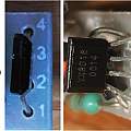
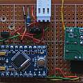
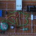
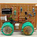
Photos, click to show full size. First one YX8018 pinout. Photo 2, standard temperature sensor board. Photo 3, YX8018 power supply.
For low cost (3 garden lights for 2 pounds) this seems a perfect solution. The battery will power a sensor for many days without light, modest sunshine soon charges it fully. The only snag I foresee is that the battery is probably not high quality and may not last long.
Super Capacitor version
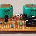
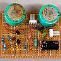
I was once told in a Physics class "You will never see a 1 Farad capacitor, it would fill this room!". So I had to buy one, if only to point at and say "I was once told...". I found 1 Farad 5.5 V Tokin capacitors on eBay - five for just over a pound. The idea is to charge the caps from a solar cell and run the sensor on the stored power.
Still using a solar cell from a garden light, I required to increase the voltage. This is because the energy stored in a capacitor is ½CV² proportional to the square of the voltage so higher voltages store more energy. For example from 5 V to 2.5 V the change in energy is 12.5 - 3.125 = 9.375 J, obviously from 2.5 to 0 V there is only 3.125 J. The range from 5 to 2.5 V is viable to power the sensor, and makes use of three quarters of the stored energy.
I built a boost converter from a couple of common transistors and some components. It has an efficiency of around 65%, and it will keep running when the output from the solar cell is as low as 10 μA. It does work (as if that proves anything) and pumps the capacitors up to 5 V when the sun shines. The circuit and discussion is here DC to DC converters.
I used two 1 Farad capacitors, a single capacitor does not have quite enough capacity to get through the night. To protect the capacitors from too high voltages I added a Zener diode across them. Unhappy with that I programmed the Arduino to turn on its LED when the voltage reaches 5 V; even then the voltage has reached 5.3 V.
If the load acts like a resistor as the voltage increases the power consumed will also go up as the square of it. A better idea would be to step the voltage back down to a constant before supplying it to the sensor.
In fact it turns out the 433 MHz transmitter module I have used in all my sensors does act like a 360 Ω resistor, at 5 V it draws 13.75 mA, at 4 V 11.21 mA, at 3 V 8.44 mA and at 2.5 V 6.89 mA. Another transmitter module the TX5 from the Chinese Minew company draws 11 mA at 3V and the current changes only slightly with voltage.
It will take 2(5-2.5)/0.008 = 625 seconds to discharge a 2 F capacitor at a constant 8 mA from 5 to 2.5 V (or 714 seconds at 7 mA). Another possibility is discharge at constant power for example 8 mA x 3 V = 24 mW, for which the time is 780 seconds (or 1070 seconds for 7 mA x 2.5 V = 17.5 mW) (simply take the change in energy 9.375 J mentioned above and divide by the power used). Discharge via a 360 Ω resistor using the exponential decay equation V = Vo exp(-t/RC) predicts a time of 500 seconds.
In practice it took 18 hours for the capacitor voltage to decline from 4.8 V to 2.4 V and a further 6 hours for it to reach 2.2 V. There are 64800 seconds in 18 hours, the ratio between this and 500 is 129. However the sensor only transmits for 200 ms once every 40 seconds; predicting a ratio of 200; since the transmitter does not transmit all the time the ratio should be higher. These numbers are close enough, some energy is used by the micro-controller and the capacitors self-discharge a little.
The conclusion is that using a DCDC converter to step the voltage from the capacitor down to a constant 2.5 V the run time could be doubled if the converter was 100% efficient. A 90% efficient circuit is shown here.
What happened 1st November 2015
The above was written in March 2015 just as the days started to get longer, it was little surprise the sensor worked well through the summer. 1st November was dull and misty with no sun, despite that the sensor worked for the full 24 hours with a maximum voltage of 3.5 V and a minimum of 2.6 V. The next day with a short sunshine break it was back to 5 V. All of which backs up the theory; as the voltage goes down power use also drops.
On the 9th of November (heavy rain all day) the maximum voltage was 2.9 V and the minimum 2.2 V. The difference in energy is 3.6 J. It would be reasonable to assume there was no charge from the solar cell for between 12 and 15 hours, which would give a power consumption between 66 and 83 μW; much as predicted.
In the six months cheap super caps on ebay have gone from 1 F to 500 F; at first sight that changes everything. These new caps are 2.7 V; storing one quarter per Farad (at 2.7 V) of what the 5 V caps can. Even so a 500 F cap will store 125 times as much energy as a 1 F. Given 2 F (at 5 V) allows sensor operation for one day, 500 F should provide 60 days duration.
A 40 mAH battery (as in the garden lights) has an energy capacity of 180 J. A 500 F capacitor a capacity of 1800 J.
Design would be a charge voltage limiter and a boost converter. A bit like the garden light based solar sensor.
I bought a couple of 100 F capacitors, the physical dimensions of the 500 F ones being too large for sensors. Self discharge appears to be a big problem, a capacitor charged to 2 V, had 12 hours later declined to 1.2 V.
What happened 10th December 2015
The garden light version stopped working having completely discharged its battery. November and December 2015 have been very dark; the wettest day ever recorded in England occurred with over a foot of rain in the (nearby) Lake District. Presumably the failings are using too much power keeping the boost converter going all the time and not being able to reduce transmitter power by operating it at a lower voltage when there is not much energy left.
Investigation of the garden light version showed a standby current around 80 μA a lot more than the 20 μA mentioned at the start. Replacing the yx8018 with the one I'd first tested reduced the current drawn to around the 20 μA figure. Under the low light conditions for the long period mentioned the standby current has been too big. Using one of the designs on the DCDC page would have given better results.
Surprisingly the super capacitor version is the winner.
