Started 4th April 2022
I set my 3D printer going and returned to my PC, turning round a few minutes later I was greeted by smoke. A quick glance at the screen revealed a temperature of 273 °C (the temperature set for the print job was 200 °C). A moment of wondering what to do and I hit the reset button. This left me with no idea what had gone on. I restarted the print and it completed normally.
I found that Marlin 2 has a default temperature limit of 275 °C built in, something I then changed to a much smaller value (235 °C). I'd set the print going with the hotend very close to the bed, perhaps liquid filament had oozed out and thermally joined bed and nozzle provoking the PID temperature code to go to extremes.
Mostly firmware uses a PID algorithm to reach the required temperature, this understands the thermal inertia of the hotend, it is legitimate for there to be some overshoot - going past the set temperature is by design. Marlin only panics when the temperature goes past the maximum value, quoting the source code:
// Above this temperature the heater will be switched off.
// This can protect components from overheating, but NOT from shorts and failures.
// (Use MINTEMP for thermistor short/failure protection.)
#define HEATER_0_MAXTEMP 235
An alternative to PID is "bang-bang" mode which turns on and off at a fixed temperature difference to the target temperature.
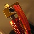
Maybe there was an intermittent electronic failure. I subsequently replaced much of the electronics (Arduino Mega 2560 plus RAMPS 1.4). As a result of the high temperatures filament had covered most of the hot end and that also got replaced with a new one.
This counts as a near miss, after many years of 3D printing I'd become accustomed to it being reliable. But as I wrote (here) when I started, there are simple failure modes which will possibly lead to disaster.
As ever you follow what is written here at your own risk. I found Octoprint Safety Printer plugin covered much the same ground and provided ideas.
Physically based hardware protection is superior to the software based ideas here. For example it must be possible to devise electronics that can detect a MOSFET has gone short circuit and is no longer responding to control signals. But that's all too difficult, so one puts ones faith in software.
The idea is that software detects something is wrong and turns the power to the printer off - there is a mechanism to turn the power off outside the ones used in normal operation. To do this the power to the printer is delivered via an electronically controlled switch (e.g. a relay). The switch can be in the low voltage power supply inside the printer or (better) in the mains supply. To get the printer to start up there has to be a way of getting power to turn the switch on - e.g. a push button that temporarily shorts out relay contacts.
A big box with a relay and lots of mains wiring did not appeal to me, and neither did routing the high currents to the hotend and heated bed via a relay. I picked remote control mains sockets, to start with these are 433MHz radio controlled - like cordless doorbells - it is easy to operate them using an Arduino.
Level 0
Set up the Marlin software correctly, turn on thermal runaway detection, set the max temperature to something sensible.
Level 1
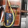
Use an Arduino Pro Mini to monitor the existing thermistors for the hotend and heated bed and turn off the remote control mains socket in case of over temperature (using a generic 433 MHz transmitter). The printer can be turned on using the remote control device that comes with the sockets. I am suggesting connecting the analogue inputs of the Pro Mini in parallel with those of the normal printer micro-controller. The Pro Mini is independent of the microcontroller running the printer and anything else like OctoPrint.
Level 2
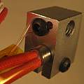
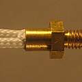
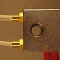
Like level 1, but add duplicate thermistors for the Pro Mini. The typical hotend has a hole which a thermistor is pushed in, another hole takes an M3 bolt which with a washer holds the wires to the thermistor. This is not a good idea, only if you're lucky will the thermistor reliably touch the metal of the hotend. A better idea are screw in threaded thermistors which can be retrofitted using the existing M3 holes. It is easy to drill and tap a second M3 hole for another thermistor. I found in my collection of used hotends one with two sets of thermistor holes (photo #7) - somewhere dual thermistors must have been standard.
Level 3
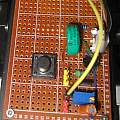
Like level 2, but add a way of generating power to start up the Pro Mini and allow it to tell the remote control socket to turn the power on. I used a NiMh battery from an old timer clock, power from this is fed via a push button (on) switch to a YX8018 LED driver (take from a solar powered garden light) which generates 3.3 V to power the Pro Mini. Power from the YX8018 goes to the Pro Mini Vcc pin. The 3D printer 5 V supply goes to the Pro Mini Raw pin. This 5 V supply also keeps the NiMh battery charged. I am using a 3.3 V Pro Mini because I want to connect it to a Raspberry Pi.
