started 15th March 2020
See also PUT part 1 and PUT part 2
SCR Oscillator
A Programmable Unijunction Transistor (PUT) is a four layer pnpn device as is a thyristor aka Silicon Controlled Rectifier (SCR). The difference is which layer is connected to the gate - for a PUT p(A)n(G)pn(C) for an SCR p(A)np(G)n(C) - where A is the anode, C cathode and G the gate. Looking at the transistor equivalent circuit.
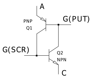
For the PUT taking the gate negative enough with respect to the anode turns the device on, for the SCR taking the gate positive enough with respect to the cathode turns it on.
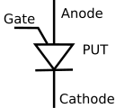
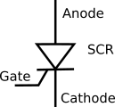
Symbols:
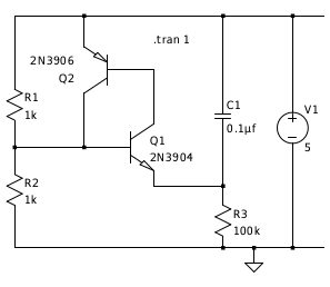
From the circuit for the PUT oscillator:
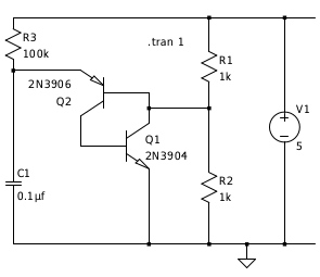
symmetry gives an oscillator circuit for the SCR:
Or with a real SCR:
(a 2N6027 is a PUT, however the ones I got from ebay were SCRs and work in this circuit).
PUT Pulse stretcher
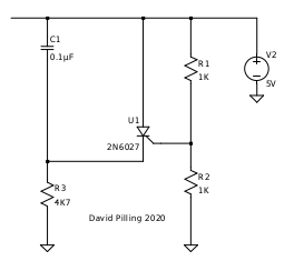
Imagine you have a vibration switch that outputs pulses and a micro-controller that can't see them because they are too fast. The micro-controller interface is a single pin which has a pull up resistor giving 5 V through a 10 K resistor, this is the only power available. To signal to the micro-controller the pin has to be pulled close to 0 V.
This circuit does the trick. In the 'scope traces, yellow is the switch signal and red the voltage across the circuit equal to the signal on the micro-controller input pin.


It is possible to replace the diode with a 100 K resistor, the pulse is then a bit shorter.
You could look at this circuit as using a monostable to debounce a switch. However the novelty is having no independent power supply, just the power that is used to sense the switch state - I am sat outside a black box and I choose not to enter it or have an external power source.