Started 21st Feb 2020
After finding how sensitive the ITR9606 opto interrupter is to changes in position when operated in a linear mode instead of the usual on/off switching mode I made a practical device out of it, in the form of a 3D printer Z axis probe.
My idea is to block the slot in the opto interrupter with a piece of material (I'll call it a shutter) attached to the core of a push pull solenoid. A push pull solenoid has a spring, when there is no current flowing the spring pushes the core out of the coil, when current flows magnetism pulls the core in and compresses the spring. By varying the current in the solenoid I can position the shutter so that it partially blocks the opto interrupter at the point which is most sensitive to changes in position. The output from the opto interrupter indicates the position. The arrangement is such that when the core is fully drawn into the solenoid the shutter clears the slot and when the spring is expanded the slot is blocked.
When the slot is blocked, the opto interrupter output is high and when the slot is clear the output is low. So if the output is high the current through the solenoid needs to be increased and when the output is low the current needs to be decreased. Somewhere between these two extremes there is a current which gives a middle value for the opto interrupter output.
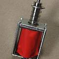
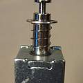
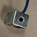
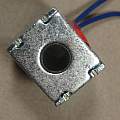
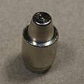
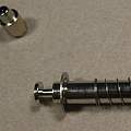
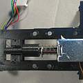
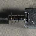
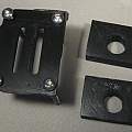
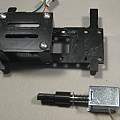
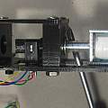
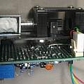
I obtained the solenoid from ebay[1]. It was designed to snap into the core drawn in position by having a piece of iron riveted to the bottom inside the solenoid - I drilled this rivet out (photo 5 shows the piece of iron). This both gave me more linear operation and allowed a probe to emerge through the resulting hole (photo 3).
If the opto interrupter is being powered from 0 to V volts then the desired output is V/2 or if the supply is denoted -V to V then the desired output is 0 - either way the deviation from the desired value can be called the error. My first idea was to take the error apply a lot of gain and apply it to the solenoid - at some point the error multiplied by the gain will be enough to make the solenoid maintain the error value. When I tried this I got oscillations - about 30 Hz - and I had visions of there being a lot of mechanical Physics involved in a solution - mass on a spring and all that.
I searched for magnetic levitation circuits to see how they worked - [2] provided me with all I needed. The previous idea is known as proportional control, some derivative information has to be added. This is easy only needing a resistor and capacitor and it stopped the oscillation.
I set out to sense the print bed of my 3D printer, contact will apply an outside force to the solenoid core via a probe, this force will alter the core position and changing solenoid current will not be able to restore the correct position. To detect this I could add a comparator and look for the change in output from the opto interrupter, but that requires calibrating the system aka 'pot twiddling'.
A better idea to is to give the system some memory so that it knows when the position is being changed. To do this the error is fed to an integrator the output of which feeds the solenoid. The result of feedback is that the error is reduced to zero - at least whilst there is no external force. If something pushes the solenoid core then the error is non zero and the output of the integrator becomes maximal - both conditions easy to recognise with a comparator.
The proportional and derivative drives are still needed, the combination is known as a proportional–integral–derivative or PID controller (wikipedia).
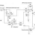
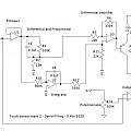
Schematic diagrams:
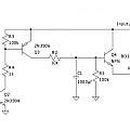
The second schematic is of the "power supply" the 12 V printer power is noisy, I fixed this by using a capacitance multiplier [3] and combined this with hardware for switching the power on and off. Typically a micro-controller pin with a range of 0..5 V is going to deploy and stow the probe.
The first schematic is of the main circuit, it uses 4 op-amps. The output is designed to connect to a micro-controller pin with a built in pull-up resistor, it can only sink current. When the probe touches something the output will sink current and the micro-controller pin will go low. A potentiometer R14 sets the comparator trigger point - effectively this is the sensitivity of the probe. It can be made very sensitive, such that stamping on the floor nearby will trigger it. There is a lot of vibration in a 3D printer which means the sensitivity needs reducing.
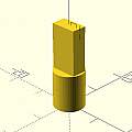
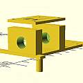
3D print files:
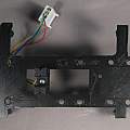
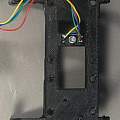
The slotted plate is designed to bolt on to my E3D v6 Bowden Mount.
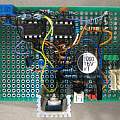
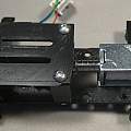
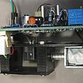
Photos:
G-code M48 makes the printer perform a test of the repeatability of Z axis probing. Executing M48 P10 v4, typical results are:
Mean: 0.019875 Min: 0.016 Max: 0.022 Range: 0.007
Standard Deviation: 0.002050
These should be compared with the results on the Z Probing page, they're respectable but not quite as good as the best inductive probe.
Operating force is a few gm. The solenoid has a maximum force of 6 gm in the position the electronics maintain. When the bed begins to push the probe, the electronics attempt to increase the force being exerted by the solenoid, this "taking up the strain" process means probe movement without any triggering is possible.
The solenoid can be characterised by the size of the throw - how far it moves - that distance is the difference between where the probe is when deployed and when stowed. Because some range is required to adjust the opto interrupter not all the throw is available. Another parameter is the "slop" how close a fit the core is - the one I used was quite sloppy and I ended up designing a 3D printed "bearing" to reduce movement.
When the probe is deployed and the opto interrupter position is being maintained forces are in balance and only a tiny additional force would cause movement. I assume that the more of the core is drawn into the solenoid the greater the force needed to move it.
The solenoid is doing two jobs, firstly it is seeking out the small sensitive position in the opto interrupter, secondly it is deploying the probe - moving it below and above the printer nozzle.
(1 Newton is equal to 101.97 grams weight)
Marlin firmware:
I set up these lines in configuration.h
#define Z_MIN_ENDSTOP_INVERTING true
#define Z_MIN_PROBE_ENDSTOP_INVERTING true

#define DELAY_BEFORE_PROBING 2400
#define SOLENOID_PROBE
#define SOL1_PIN 44
Mark 2
In the above circuit the comparator is not looking at the output of the opto interrupter, rather it is monitoring an integrated version of the error. Changing this gives results as good as those of inductive probes:
Mean: -0.047625 Min: -0.049 Max: -0.046 Range: 0.003 Standard Deviation: 0.000919
This time Marlin needs:
#define Z_MIN_ENDSTOP_INVERTING false
#define Z_MIN_PROBE_ENDSTOP_INVERTING false
Schematic diagram:
Postscript
A problem with this design is its weight, at 60gm and hanging off the outside edge of the print-head it tended to make the print-head wobble. A BL-touch is around 10gm. An inductive probe is 50gm. A bit too chunky a design, and too much material lavished on the electronics. But that is a problem of implementation, the idea is fine.
An insight is that detecting any probe movement whatsoever is not important, it is OK for the probe to move 2 mm after contact and before triggering, what matters is that the trigger point is consistent. That observation undoes much of the above complication - why bother flying the probe at the most sensitive point of the opto sensor, just apply maximum power and then watch the output voltage and trigger as it crosses the mid-point. What can be said about the above design is that it applies the minimum force to sense the bed. It also produced the best figures for the M48 test that I have found.
Links:
- "DC 6V-12V Micro Mini Solenoid Electromagnet Actuator Open Frame Suction Type Rod"
- Barry's Magnetic Levitation
- A Simple Capacitance Multiplier Power Supply For Class-A Amplifiers
