Started 19th October 2017
Build log for my Hypercube Evolution printer - which took from June until October 2017
After improving my cheap ebay 3D printer until it was so ramshackle I had no confidence it would work for long, I decided to build something better. The Hypercube Evolution (HEVO) [1] appealed because I had come to the conclusion a 3D printer had to be rigid and accelerate as little mass as possible. The Core XY design of the HEVO meets both these requirements.
Deciding the size, I didn't really want anything bigger than the standard 210 mm square, but there was the temptation to future proof by making it bigger. I didn't want to cut linear rails and so used the available sizes to set the dimensions of the printer. For the X axis I opted for 450 mm rails and for Y and Z 400 mm. This translated to 3030 extrusions 400 (x4), 420 (x6) and 500 mm (x4) long. I built the dual Z axis version, but used stepper motors with couplers and 300 mm lead screws. The "cube" is 500 mm high, 460 mm deep and 480 mm wide. I call the cube face with the two XY motors on, the front. When talking about left and right I am facing the front. As is standard the X rails are 8 mm diameter, Y rails 10 mm and Z rails 12 mm.
I sourced all the parts from ebay and Aliexpress except for the 3030 and 2020 extrusions which came from a local UK supplier KJN. Of the ebay and Aliexpress items everything except for some bolts came direct from China.
The full "BOM" is given below, I've included prices for interest, but things change fast. When I started T nuts could only be had on Aliexpress, a couple of months later they had appeared on ebay at much lower prices. Perhaps my BOM will clear up some ambiguity in the official design. But it does not include everything. I used two stepper motors from my ebay printer for the Z axis (I'd replaced them with higher resolution ones). I have stock of m3 nuts and bolts and electronic components.
I had two kits each consisting of 2 motor pulleys and 2 m of timing belt. Each 2 m belt nicely fitted the printer, with around 300 mm spare. In other words it needs 2 x 2 m of belt. Only 2 motor pulleys in total are needed (I'd used the 2 spare ones on my ebay printer).
I got 100 x 3030 T nuts and 50 x 2020 T nuts and then 150 bolts to fit. This is about right, I used just over 50 x 3030 nuts on the frame and then set off using them to hold on things like the power supply and electronics.
I printed various additions, a mount for the power supply [2], a power switch case [3], a mount for the 12864 LCD [4] and a bracket to hold the mk8 extruder and motor [5]. I modified the power supply mount to allow the power supply case to be slightly above the surface the printer sits on. Routing the stepper wires through the 3030 slots made things tidier and involved printing lots of slot covers [6].
I also created a few pieces of my own. A mount for the Arduino Mega and a similar mount for 50 x 70 mm electronic protoboards. Modified brackets for the LCD and the power supply, these are for use in conjunction with the parts from thingiverse. The power supply brackets allows the power supply case to be slightly above the surface the printer sits on. This collection of mounts/brackets can be downloaded from the following link.
I fitted two X and Y optical endstop switches as per the design and for completeness. I have yet to get more than one for each axis to work. The ones that work are min X (left hand) and min Y (front). That puts the origin (X=0, Y=0) at the front left hand corner of the bed. X increases to the right, and Y to the back. Z increases as the bed moves downwards. Z=0 is when the bed is at its maximum height and the nozzle is touching the bed.
Having devised a strain gauge based Z probe (see Z probing) I wanted to use the same thing on this printer. This meant using my own E3D v6 Bowden mount, to do that I designed a plate which fits the HEVO X carriage. Since my hotend mount is wider than the X carriage I also had to produce some adjustable X endstops - allowing me to reduce the amount of X travel.
The strain gauge Z probe consists of the plate that attaches to the standard HEVO X carriage, the back and the front of the E3D v6 hotend mount and the adjustable X endstops. All these can be downloaded from the link below.
Implementation is the same as for the ebay printer (see Z probing), there's an Arduino Pro Mini which emulates a Z axis endstop switch by looking at the signals to the Z axis stepper motor driver along with the output from the HX 711 ADC which is connected to a strain gauge stuck to the hotend mount. The software can be downloaded from the link below - I had to make some modifications for this printer.
Downloads:
- Arduino project StrainStop05 - 5th November 2017
- OpenSCAD files for Bowden E3D v6 hotend mount, X carriage plate and adjustable X endstops (5th November 2017)
Compared to the ebay kit printer, this one seemed hard work. For example on the ebay printer I was given the power plug socket along with wires, bolts and somewhere to fit it. Total time five minutes. Here I had to work out which socket I needed, buy it off ebay. Then discover it didn't come with a fuse, and the fuse is not a standard UK plug one, so I have to buy some 20 mm x 5 mm fuses off ebay, along with working out how big a fuse I need. On top of that I had to print a box [3] from Thingiverse to put the socket in. On the upside whilst doing all this messing about I did learn the ebay printer has bare metal connected to the live side of the mains.
Following the plans I used parts with brass 'knurls', I was not happy with them. Having worked to print perfect parts I then started spoiling them with a hot soldering iron. As it happened I did not have to do any reprints and the knurls held the forces. On Thingiverse there are now alternative knurl free components. Although knurls sound OK, in practice things always went wrong, the plastic would shrink away from them, and in some parts the plastic layers around the knurl are thin. Early experiments indicated I would need temperatures lower than the minimum on my soldering iron, as a result I built a low temperature soldering iron controller (see Solder). In reality the plastic parts are substantial and need a lot of heat to melt sufficiently for the knurl to go in.
On one of the first test runs I watched the hotend temperature climb past the expected value, and complacently thought it would be a badly tuned PID and the computer would soon turn the power off. The temperature got to 300 °C before I switched the printer off. The cause of this was a MOSFET on the RAMPS board failing. The RAMPS boards have 55NF06 MOSFETs, I set out to replace all three with IRLB3034pbf, a much better MOSFET. Carrying out measurements there seemed little difference, whilst the threshold voltages of my pack of IRLB3034pbf covered a wide (out of specification) range. This brought to mind "if it can be faked, it will be faked" [7]. At 12 V the hot end consumes about 2.8 A.
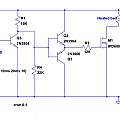
Experience with the ebay printer was that the heated bed temperature was limited by electrical losses. Connectors and cables became warm. I decided to put the heated bed MOSFET on a separate board and use substantial cables and connections (visible in one of the photos below). However I wanted to drive this MOSFET from the RAMPS output - allowing me to keep standard hardware and software. I designed a little circuit, an inverter and MOSFET driver inspired by [8].
Download
With a power supply of 12 V, I observed a current of 7.8 A at 11.4 V at the heated bed, losing about 0.1 V on each cable run - power in and out x two cables - and around the same on the MOSFET. On the ebay printer I got 10.7 V - with similar losses on the wire.
Pictures, click the thumbnails to see big versions, you'll find the big versions then have a link "click for high res. version" which will let you see an even bigger image.
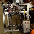
All the electronics apart from the LCD display are on the right hand side.
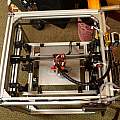
View from above. I used 25 mm bed brackets but I did not follow the plans. Two of my pieces of 2020 are 420 mm long as per design, the other two are 260 mm. For a small bed this gives more stability.
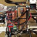
Close up of the electronics. In addition to the RAMPS board and Arduino Mega, I have two pieces of protoboard. The top one has an Arduino Pro Mini which is doing the strain gauge Z probe stuff. The bottom one is a MOSFET switch for the heated bed.
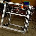
Front view
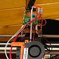
Close up of the hot end. I used self tapping screws to attach a piece of 50 x 70 mm protoboard to my X axis plate. This board contains the HX 711 ADC for the Z axis strain gauge probe, in addition it acts as a junction box for the signals going into and out of the hotend. More cables come in to this board from hot end devices than need to go out to the main board - for example there's no need to have separate earth wires from the main board for each endstop sensor, the thermistor etc. Everything hot end related is connected to this panel. On the ebay printer I found that a failed thermistor (or heater etc) would mean tracing wires back to the main board. It does not show up well in the photo that I used Dupont push fit connectors for all connections except the heater power (12 V and switched) which respecting the high currents involved use a screw terminal block.
Hotend device connections
2x (X endstop, earth, 5 V and signal)
Thermistor, earth and sense
Heater switched power and 12V
Heatsink fan, earth and 12V
Part fan, switched power and 12V
HX711 earth, 5 V, data and clock
Strain gauge 2 x sense
Hotend connections to main board
5 V
12 V
earth
2 x (X endstop signal)
Thermistor sense
Part fan switched power
Heater switched power
HX 711 data and clock
The BOM (prices include tax and carriage)
4 x 3030 x 2 m profile
1 x 2020 x 2 m profile
Cost £95.35. I had some left, but not an unreasonable amount. I bought 2 m lengths just because it was a round number and seemed reasonable for storage and transport, but making the lengths slightly greater than 2 m would have made for more efficient cutting and cost no extra.
20 x 3030 corner fitting angle aluminium 35 x 35 L connector bracket fastener £8.56
22 x T slot L type 90 degree EU standard 3030 aluminum profile Inside corner connector bracket with M6 screws £13.45
10 x Stainless Steel Cylindrical Pin Locating Pin M3*12 £1.44
GT2 Pulley 6 mm width, 3 mm bore, with teeth 20 T x 6, without teeth x 3 £5.31
M5 T nut Hammer Head 2020 x 50, 3030 x 100 £13.71
M5 / 5MM A2 STAINLESS STEEL SOCKET BUTTON / DOME HEAD ALLEN SCREW BOLTS ISO 7380
( 111283565614 ) Bolt Size: 10 mm Type: M5 / 5 mm Your Pack quantity: 100 £3.39
M4 M5 M6 M8 A2 STAINLESS HEX SOCKET BUTTON HEAD ALLEN BOLTS SCREWS SCREW ISO7380
( 321231673127 ) Screw Length (Excluding Head): 10 mm Pack Quantity: 30 Thread Diameter: M6
M5 / 5MM A2 STAINLESS STEEL SOCKET BUTTON / DOME HEAD ALLEN SCREW BOLTS ISO 7380 £2.09
MTGATHER 340pcs Suleve M3SS1 M3 Stainless Hex Socket Button Head Screws Allen Bolt Nut Assortment Kit Best Price £5.17
M3x5mm(L)-5mm(OD) Metric Threaded Brass Knurl Round Insert Nuts 100pcs PK £1.68
DualPower Aluminum Board PCB Heat Bed Heatbed RepRap Mendel Prusa 3D Printer PK £7.17
Borosilicate Glass Plate Size 213 x 200 x 3 mm £6.65
4 x 400 mm x 12 mm linear rail, £19.96
2 x 400 mm x 10 mm linear rail, £8.78
2 x 450 mm x 8 mm linear rail, £8.46
8 x LM12UU 12 mm linear bearing £5.67
4 x LM10UU 10 mm linear bearing £3.15
12 x LM8UU 8 mm linear bearing (didn't use all 12) £4.72
2 x 5 mm x 8 mm flexible coupling £1.98
MK8 Extruder Kit £2.69
2 x (kit of 2 pcs GT2 Pulley 16Teeth 5 mm + 2M GT2 Timing Belt) £6.30
2 x 300 mm x 8 mm lead screw £7.28
12864 LCD display controller + adapter £7.71
RAMPS 1.4 Control Board + 5X A4988 Stepstick £6.35
Arduino Mega £5.42
400W 12 V Power Supply Driver for LED Strip Light £12.45
4 x Optical Endstop Switch £3.32
Kit of 14 pcs wiring cables for RAMPS £3.13
3 Pin IEC320 C14 Inlet Module Plug Fuse Switch £0.81
50 mm x 15 mm 12V radial fan £0.99
3 x Stepper Motor-58 oz.in (400 steps/rev)-JK42HM40-1684 £31.88
The Poscscript (April 2020)
On the whole things have turned out well, I'm still using the printer. The main error I made was the vertical piece of protoboard with all the connections on the top, the sin here is using electrical connectors to handle mechanical forces. After about a year I had a difficult to locate problem with temperature runaway errors which was fixed by soldering the thermistor connections. Around the two and a half year mark the strain gauge Z probe became unusable - it seems the printed parts holding the hot end to the X carriage became more floppy. As a result print head movement would cause the forces from the Bowden tube and wires to bend the plastic as much as the nozzle touching the bed. I have almost always used a glass sheet coated with PEI with this printer, a change to spring steel with PEI has allowed me to use an inductive probe.
- HyperCube Evolution
- Hypercube Evolution Power supply Mount
- Hypercube Evolution Power switch Case
- Hypercube Evolution Case and Mount for 12864 LCD
- Hypercube Evolution Mk8 Bowden extruder bracket
- 3030 T-Slot Cover for Cables
- Andy Brown electronics
- MOSFET: When can we not assume that the gate current is 0?
- CoreXY Tunning
