started in earnest 10th March 2021
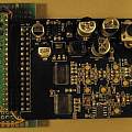
I first heard of the Alinx AN108 board on the OpenTechLab You Tube channel [3]. It is sold as an AD (analogue to digital converter) and DA (digital to analogue converter) board that needs to be driven by an FPGA (as the video says search for "FPGA AD"). I got an FPGA demo board to drive it. Of course FPGA programming strikes fear into mere software writers, the board kicked around my office floor for a couple years.
The Pi Pico has programmable io (PIO) which it is said can replace FPGA, it seemed reasonable to have a go at using one to drive the AN108.
All the difficulty is exaggerated, reading the data sheets I could have bit banged the AN108 board with any old microcontroller fast enough for my purposes, and on the Pico coding is trivial (because someone else has done the hard work).
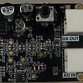
People have done FPGA drivers for the AN108 [1][2]. There is a .rar file of documentation, the schematic this contains is dated 2011. The board is powered from 5V and the signal lines are 3.3V. There is onboard voltage regulation to produce 3.3V and generation of -5V (using a MC34063A) to bias the op-amps. The AD is an AD9280 (8-bit 32 MSPS) and the DA is an AD9708 (8-bit 125 MSPS). The AD input is protected against over voltage and scales -5 V to 5V to 0 to 2 V using an AD8065 op-amp. There is a potentiometer which controls the amplitude of the DA output which is processed by a couple more AD8065s.
Whilst looking at the Pico side of things I found [4] which uses a Pico with an R2R DA driven by GPIO pins to generate waveforms. It is simple to use the code from this to drive the AN108 DA. A small change to the PIO code is needed - 8 bits of data are output and then the DA clock line is pulsed. The code is below.
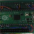
Hardware consists of the 8 signal line inputs from the AN108 connecting to the Pico along with the DA clock signal.
The next target is to copy AD output to the DA, this is a test to see if the code works rather than being useful. Again the code is below and is super simple.
For this the 8 AD outputs from the AN108 are connected to the Pico along with the AD clock signal.
I connected the DA starting at GPIO 14, the AD starting at GPIO 6 and the two clock lines at GPIO 26 and 27. The DA needs a clock signal which means the maximum possible speed is half that of the Pico clock (125 MHz). I used two PIO instructions one to write the 8 data bits and another to change the clock signal. For the AD copy to DA the best I could manage was three instructions, read, move input shift register to output shift register and write. This doesn't matter because the speed is limited by the AD and not the clock.
The software is written in Python - since all it does is set PIO code running, that is not an issue for speed.
References:


